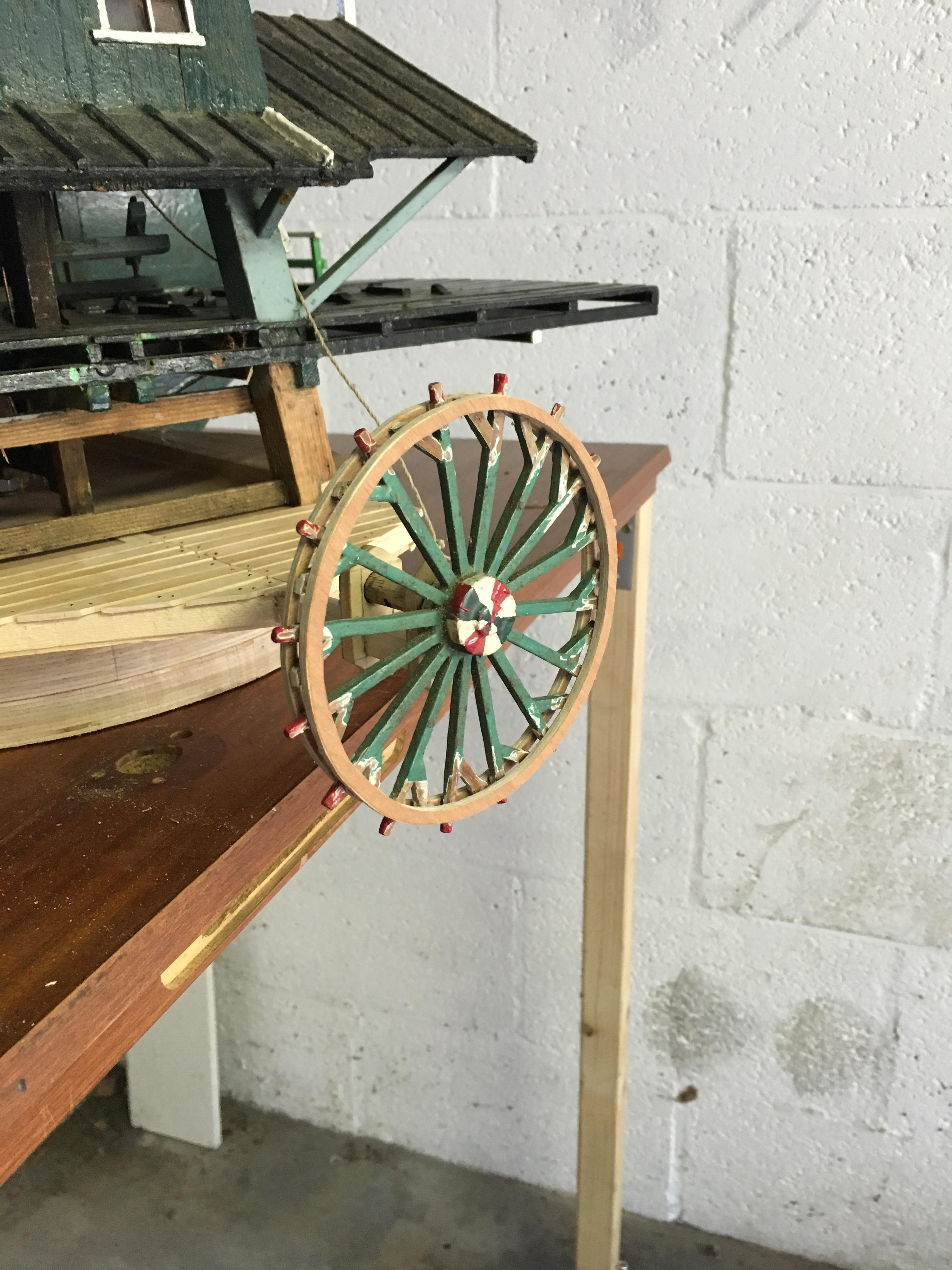
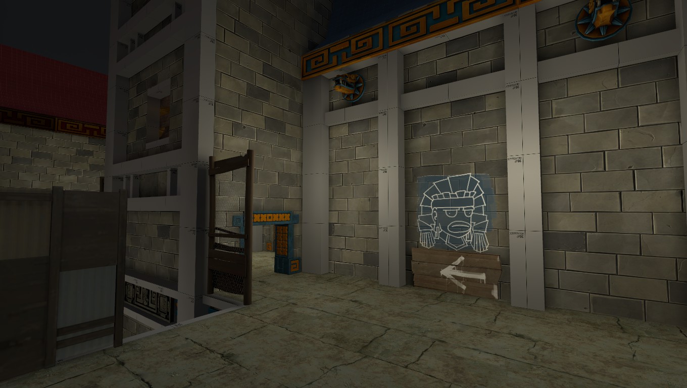
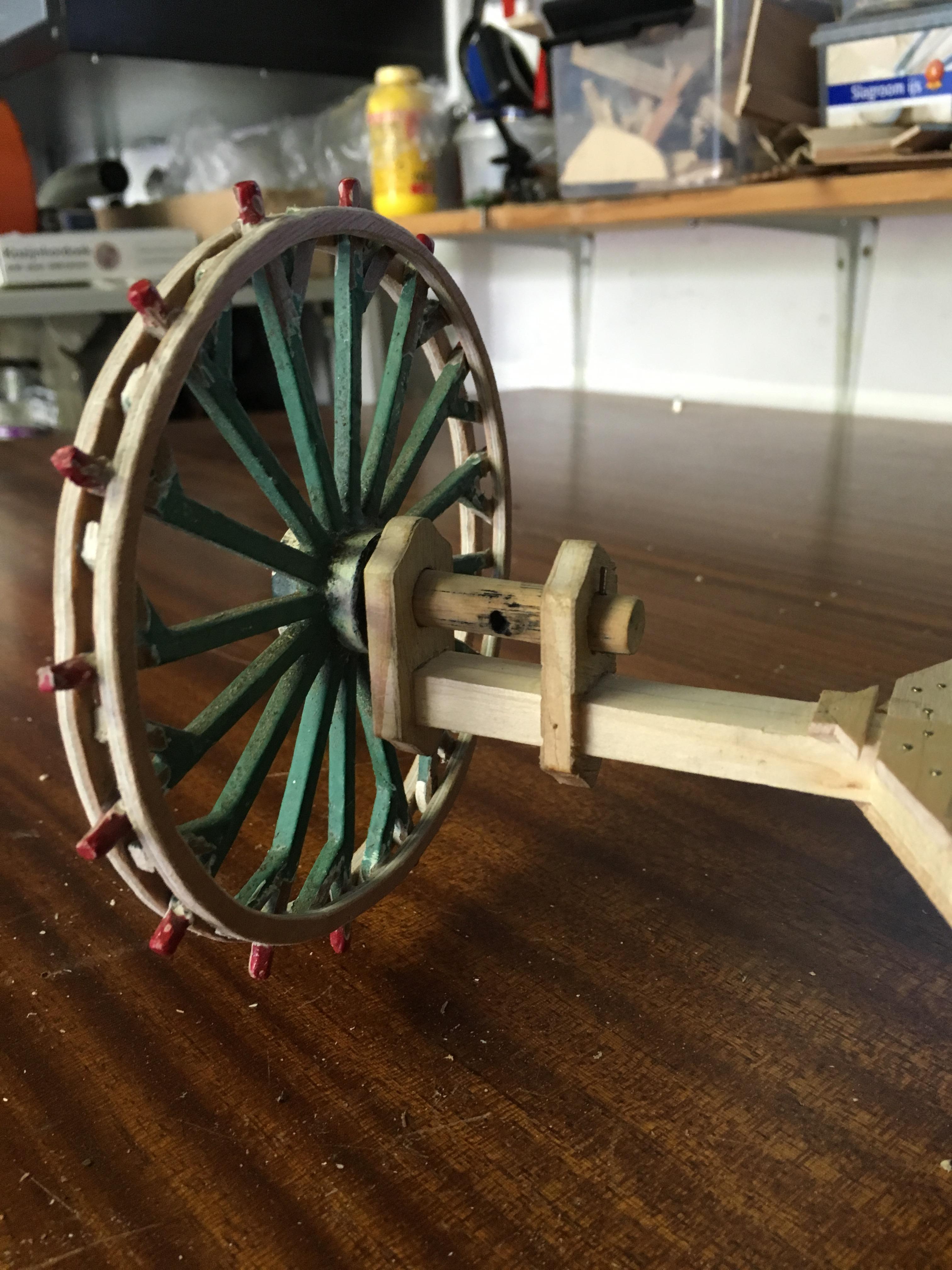
I did IRL things again. Mill's got a turning wheel again (used to put the thing into the wind), which was a bitch to create, especially the wheel's support beams (which we made like 8 versions of or something because symmetry is a bitch). Also worked on a proper braking system so it functions like it would in the real world.
Now it just needs a new coat of paint and it's good again (you can also see one of the ropes (or string, actually. We're slightly optimistic by calling it a rope) hanging out over the green diagonal beam holding part of the roof up. That braking system is explained below).
Those two support things holding the wheel's axle are the ones that failed so often. You can see why, they're in a fancy shape. Because windmills.
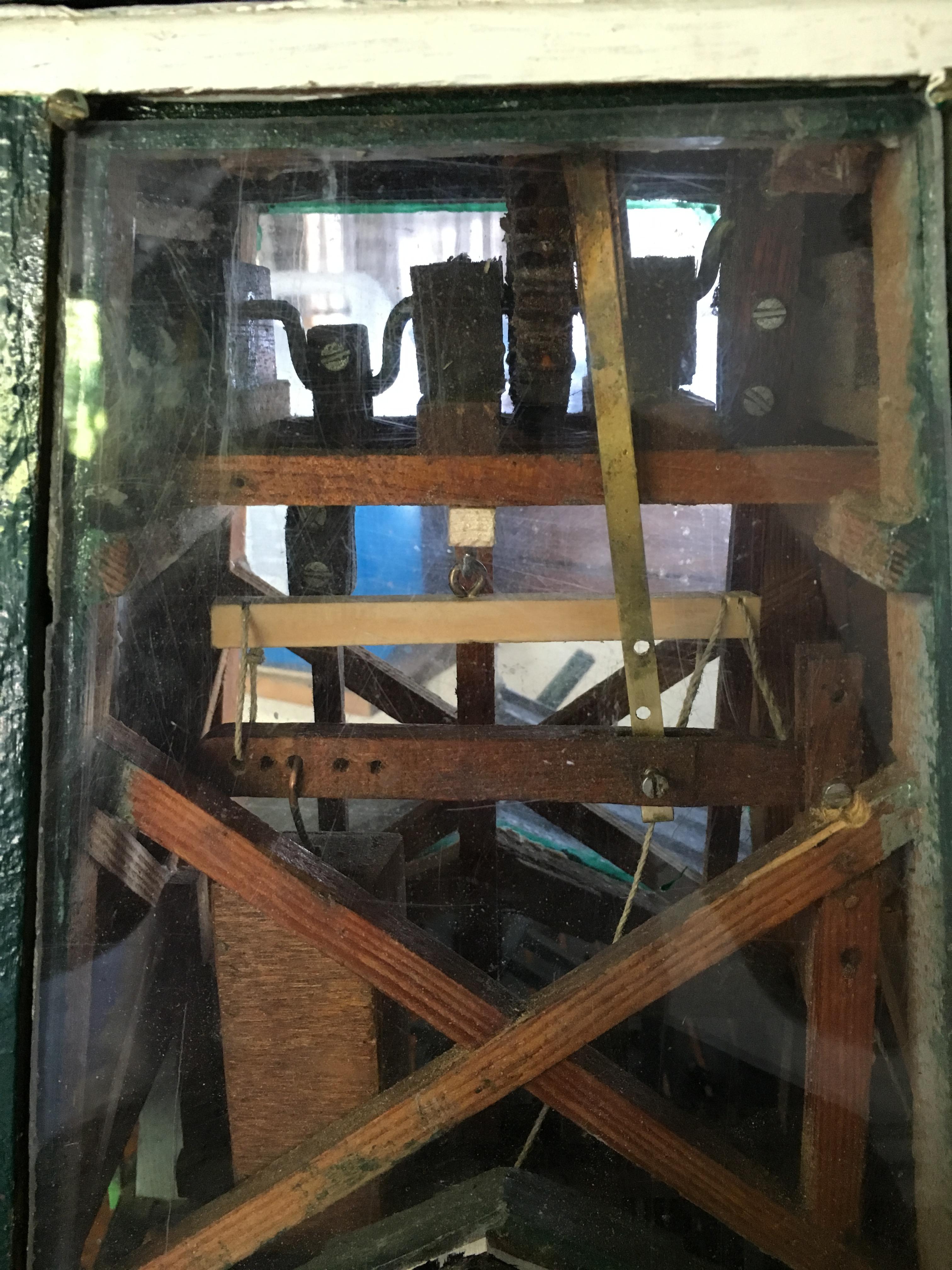
The breaking system. The white beam in the middle is hinged on a hook. On the right, 2 strings go to the bottom of the mill, one in front and one in the back (because that's what it's like originally). When one of the two strings is pulled, the right part of the beam goes down, and because of the hinge the left bit goes up. Attached to it is a dark piece of wood with holes in it on the left. Attached to that is the weight that is used to put tension on the breaking system in the top of the mill causing it to slow down and stop (and then stay stopped). That piece is hinged on a screw (visible in the far right next to the upper part of the cross beam). Slightly towards the middle, a brass strip is attached to a rounded piece of wood in the top of the mill which is sat around the wheel that also has the cogs that drive the saw blades up and down. That piece of wood is also hinged on the other side of the mill, so when the brass strip lowers down it touches down on and creates friction between that piece of wood and the cogwheel causing the sails to slow down and stop.
Holy crap is it difficult to explain a mill's complex braking system in plain English. If you still don't understand it I'll have to edit the picture to put text on it explaining it with arrows pointing what does what.