I was wondering this evening what kinds of methods you guys like to use when planning out maps; I know some people like do a couple of rough sketches whereas others will fill out a complete blueprint before even touching Hammer, and still others will jump into the editor with reckless abandon.
I have a diagram theme that I first invented while mapping for 007 Nightfire and Half-Life 2 that revolves around squared grid paper. I wanted to be able to get a concrete sense of measurements for maps which you don't get from freehand sketches - if you plan areas according to the paper grid, you know exactly how many units in Hammer to make a brush and are able to draw out new areas by comparing the scale to that of pre-existing areas.
The following is basically what my method is made out of:
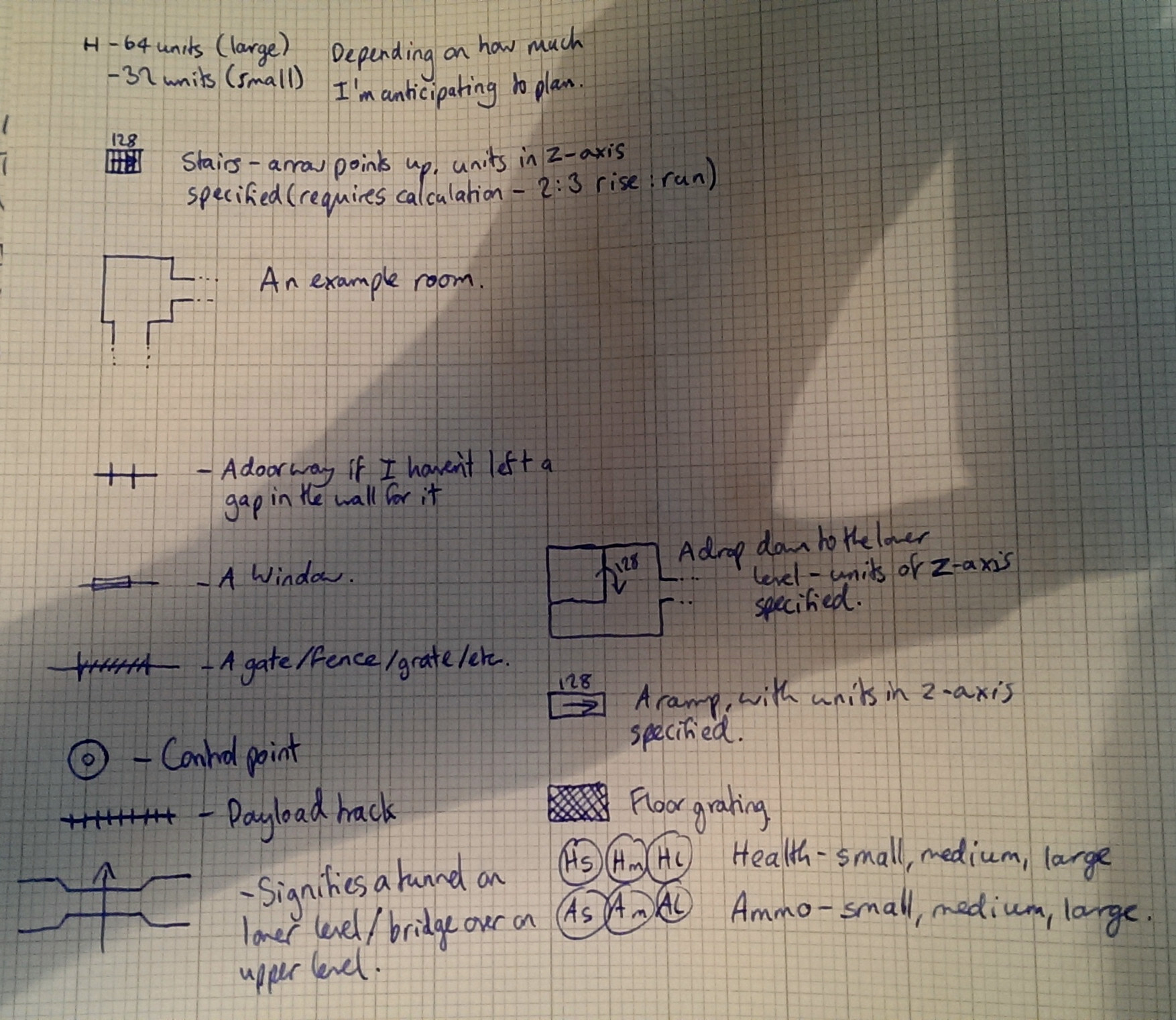
One side of a square - this can be 64 or 32 units, depending on how much space you're anticipating to take up on the page. I used to use an 8mm grid but have since switched to graph paper to be able to fit more on a page without having to sellotape multiple sheets together (and then you start to get problems with drawing on the top of tape...).
Stairs - consist of their physical area filled with vertical or horizontal lines depending on the direction of the stairs. An arrow is also present along with with the number of units these stairs ascend/descend. The arrow always points up the stairs. This method of marking stairs implicitly connects two different levels on the page, so if you have lots of stairs (particularly where they're not near each other) it can be easy to lose track of the z-level of an area in relation to the one it's connecting. You also have to calculate how long a set of stairs should be in relation to the height it ascends - I usually use the standard 2:3 ratio of rise:run.
An example room - walls are simply lines, with the brush volumes implied behind them. the physical arrangement of the brushes needed to make the room are not considered here. Corridors can be made by leaving gaps in the room walls, or by using the style below. The height of walls is not considered here, and is only implied in relation to other geometry the room may be near or part of.
Lines perpendicular to a wall specify a doorway. This can be used interchangeably with simply leaving a gap in the wall but is useful if you want to insert a corridor into a wall that you've already drawn.
Drop down - a curved arrow over a pre-existing line implies that a ledge or platform of some kind exists. The difference on the Z axis is specified. The arrow always points from the higher geometry to the lower.
Window - a thin rectangle whose length is the length of the window. Window height or distance from floor is not considered here.
Gate/fence - Some form of vertical grated plane. The height is not considered here.
Ramp - similar to stairs, the arrow points up the ramp and the distance ascended is specified. Ramps are more reliable to be able to draw that stairs, since their rise/run doesn't need to be considered as much (though care should be taken to ensure the ramp isn't too steep to walk up).
Control point - getting the dimensions right on the control point makes it easier to estimate the scale of the geometry as you draw it. I almost always start planning by drawing a control point and working outwards.
Payload track - follows lines, can curve. Isn't always easy to build a track that follows the dimensions of the track pieces in TF2 exactly.
Floor grating - specifies some sort of grating that is not vertical.
Bridge/tunnel - implies that the areas the two ends of the arrow connect are accessible to each other underneath the other geometry.
Health/ammo - H/A specifies the type of pickup, s/m/l specifies its size.
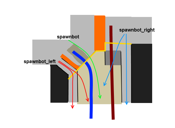
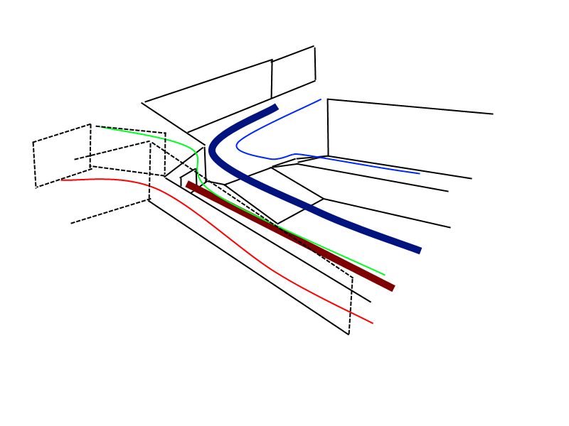
An example VSH map I planned out a short while ago:
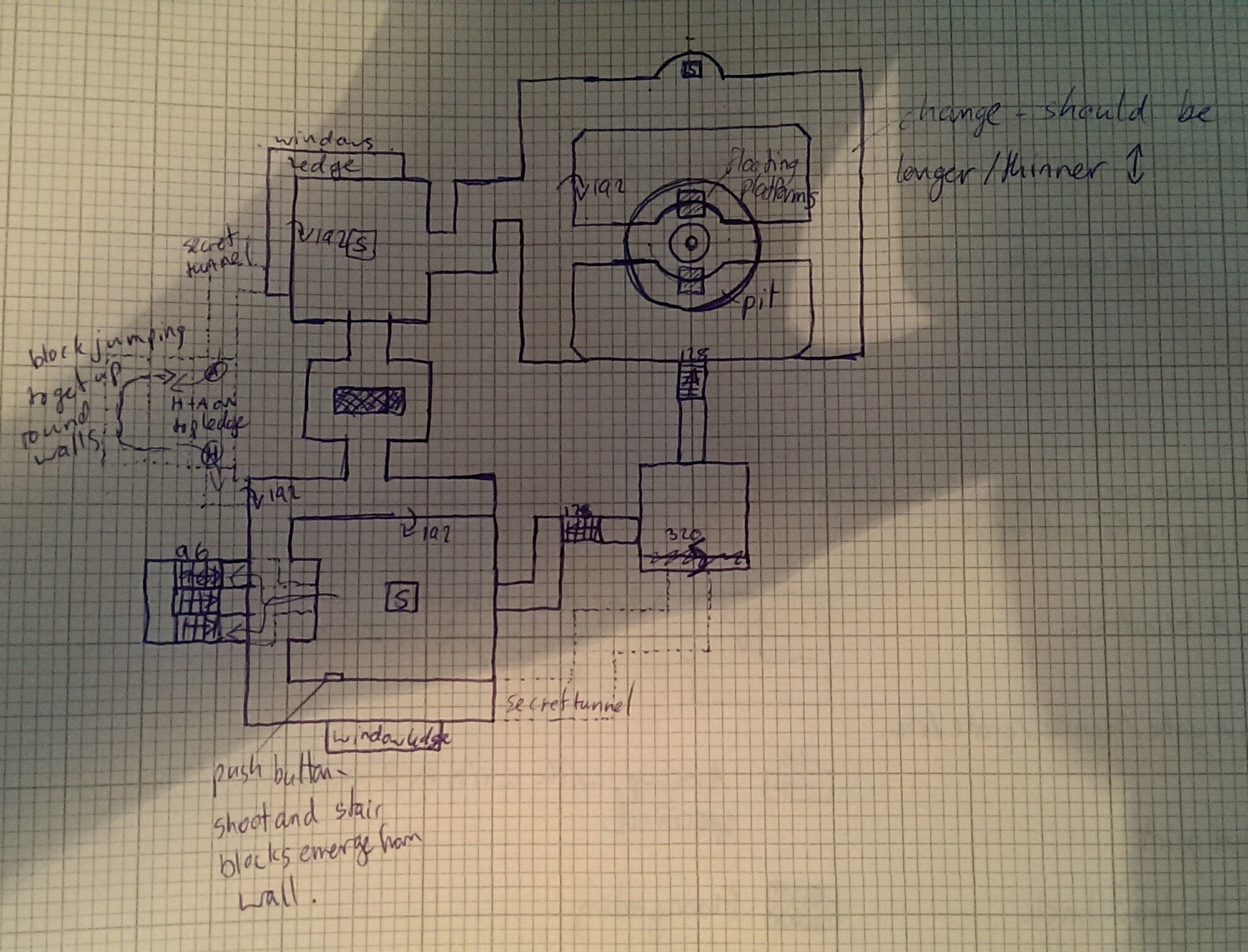
Note that this uses other arbitrary symbols like the "S" (standing for "Spongify" - this was going to utilise the textures and some of the mechanics from the old Harry Potter games). Also note that there's a big attic area that I wasn't able to draw here because it would be drawn completely over all the stuff I've already put.
Advantages of this schema:
- Simple and easy to sketch out accurate blueprints for maps.
- Measurements can be known if a scale is decided on.
- Working with a grid helps to learn the scale of a map when creating.
- Irrelevant details don't have to be decided on until creation in Hammer.
Disadvantages:
- There is a tendency to make areas too small (I think this is because you're focusing on an entire map on paper, so it's easy to "zoom out" in your head and think a small enough area is adequately sized).
- Isn't very easy to implement height differences, or draw large areas above/below a previously drawn area as you end up drawing over the top of the diagram and things get confused quickly.
- Easy to lose track of relative heights of areas.
- In certain cases symbols can be unclear (for example, if a doorway is put into a wall and the width of the corridor it connects onto is the same width as the doorway, two of the "prongs" of the doorway symbol are drawn on top of the wall lines of the corridor).
- Drawing large maps can get very unwieldy, as can looking at the pieces of paper when you go and transfer into Hammer - I once ended up with a load of taped-together 8mm grid sheets that covered an entire dining table.
I have a diagram theme that I first invented while mapping for 007 Nightfire and Half-Life 2 that revolves around squared grid paper. I wanted to be able to get a concrete sense of measurements for maps which you don't get from freehand sketches - if you plan areas according to the paper grid, you know exactly how many units in Hammer to make a brush and are able to draw out new areas by comparing the scale to that of pre-existing areas.
The following is basically what my method is made out of:
One side of a square - this can be 64 or 32 units, depending on how much space you're anticipating to take up on the page. I used to use an 8mm grid but have since switched to graph paper to be able to fit more on a page without having to sellotape multiple sheets together (and then you start to get problems with drawing on the top of tape...).
Stairs - consist of their physical area filled with vertical or horizontal lines depending on the direction of the stairs. An arrow is also present along with with the number of units these stairs ascend/descend. The arrow always points up the stairs. This method of marking stairs implicitly connects two different levels on the page, so if you have lots of stairs (particularly where they're not near each other) it can be easy to lose track of the z-level of an area in relation to the one it's connecting. You also have to calculate how long a set of stairs should be in relation to the height it ascends - I usually use the standard 2:3 ratio of rise:run.
An example room - walls are simply lines, with the brush volumes implied behind them. the physical arrangement of the brushes needed to make the room are not considered here. Corridors can be made by leaving gaps in the room walls, or by using the style below. The height of walls is not considered here, and is only implied in relation to other geometry the room may be near or part of.
Lines perpendicular to a wall specify a doorway. This can be used interchangeably with simply leaving a gap in the wall but is useful if you want to insert a corridor into a wall that you've already drawn.
Drop down - a curved arrow over a pre-existing line implies that a ledge or platform of some kind exists. The difference on the Z axis is specified. The arrow always points from the higher geometry to the lower.
Window - a thin rectangle whose length is the length of the window. Window height or distance from floor is not considered here.
Gate/fence - Some form of vertical grated plane. The height is not considered here.
Ramp - similar to stairs, the arrow points up the ramp and the distance ascended is specified. Ramps are more reliable to be able to draw that stairs, since their rise/run doesn't need to be considered as much (though care should be taken to ensure the ramp isn't too steep to walk up).
Control point - getting the dimensions right on the control point makes it easier to estimate the scale of the geometry as you draw it. I almost always start planning by drawing a control point and working outwards.
Payload track - follows lines, can curve. Isn't always easy to build a track that follows the dimensions of the track pieces in TF2 exactly.
Floor grating - specifies some sort of grating that is not vertical.
Bridge/tunnel - implies that the areas the two ends of the arrow connect are accessible to each other underneath the other geometry.
Health/ammo - H/A specifies the type of pickup, s/m/l specifies its size.
An example VSH map I planned out a short while ago:
Note that this uses other arbitrary symbols like the "S" (standing for "Spongify" - this was going to utilise the textures and some of the mechanics from the old Harry Potter games). Also note that there's a big attic area that I wasn't able to draw here because it would be drawn completely over all the stuff I've already put.
Advantages of this schema:
- Simple and easy to sketch out accurate blueprints for maps.
- Measurements can be known if a scale is decided on.
- Working with a grid helps to learn the scale of a map when creating.
- Irrelevant details don't have to be decided on until creation in Hammer.
Disadvantages:
- There is a tendency to make areas too small (I think this is because you're focusing on an entire map on paper, so it's easy to "zoom out" in your head and think a small enough area is adequately sized).
- Isn't very easy to implement height differences, or draw large areas above/below a previously drawn area as you end up drawing over the top of the diagram and things get confused quickly.
- Easy to lose track of relative heights of areas.
- In certain cases symbols can be unclear (for example, if a doorway is put into a wall and the width of the corridor it connects onto is the same width as the doorway, two of the "prongs" of the doorway symbol are drawn on top of the wall lines of the corridor).
- Drawing large maps can get very unwieldy, as can looking at the pieces of paper when you go and transfer into Hammer - I once ended up with a load of taped-together 8mm grid sheets that covered an entire dining table.
Last edited:


")