- Jan 19, 2021
- 112
- 93
The TF2 Train, HO Scale - Recreating the TF2 train as an HO Scale model. Some liberties taken.
Project Goal: Recreate the classic TF2 Train seen in Well and other maps.
Day 1
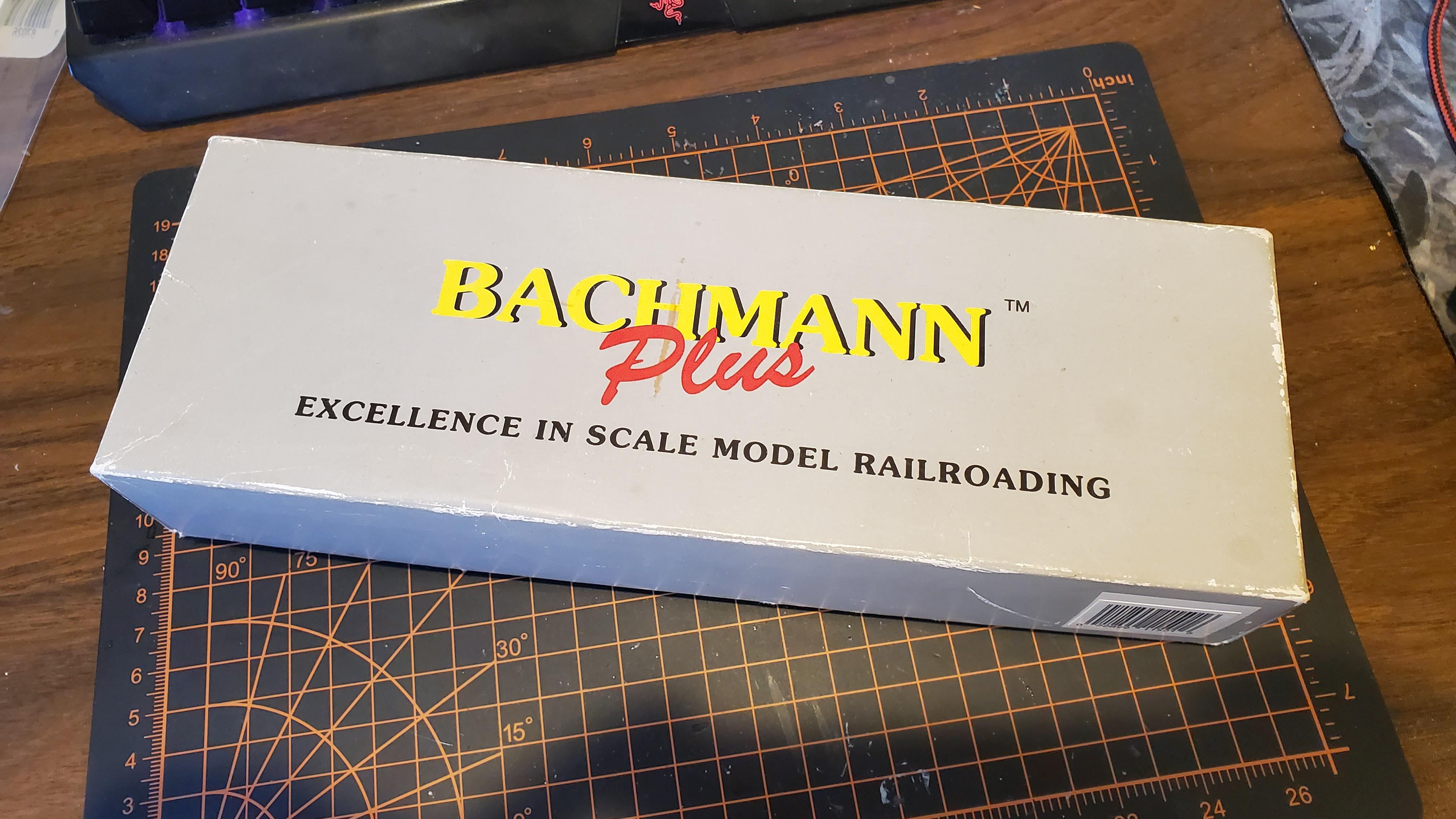
This project starts with an existing locomotive: an undecorated Bachmann Plus EMD GP35. Not the flashiest locomotive, but a nice cheap start for a project like this. I obtained this last weekend from the local youth club, gave it a test run, then shelved it till the jam start.
Today's goal was to implement all the electronics, and prep the locomotive for painting tomorrow, at the club. The decoder I started with was a DigiTrax DH123D. An older decoder, but considering its been sitting in a box for about 8 years, what better time to use it than now?
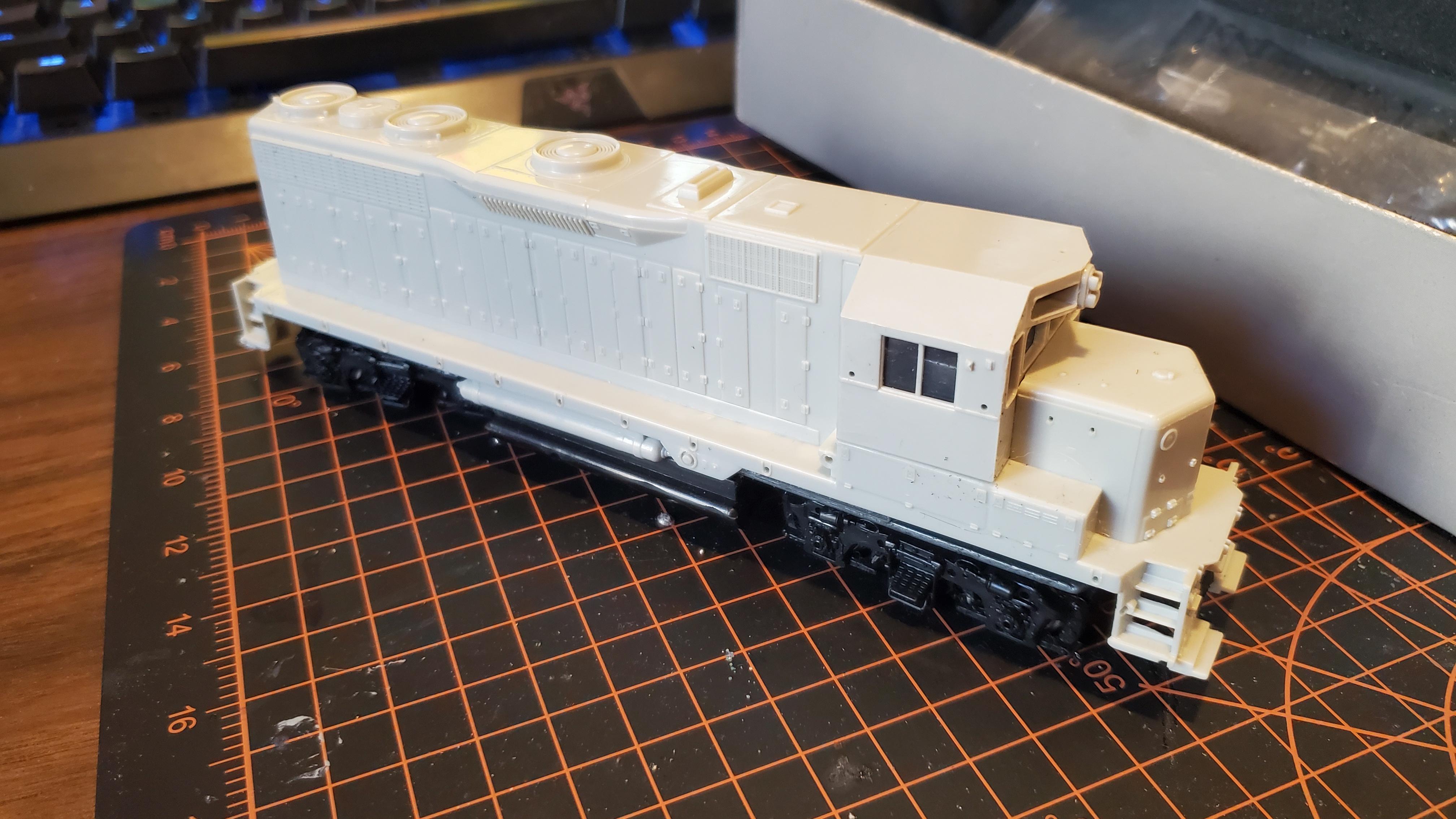
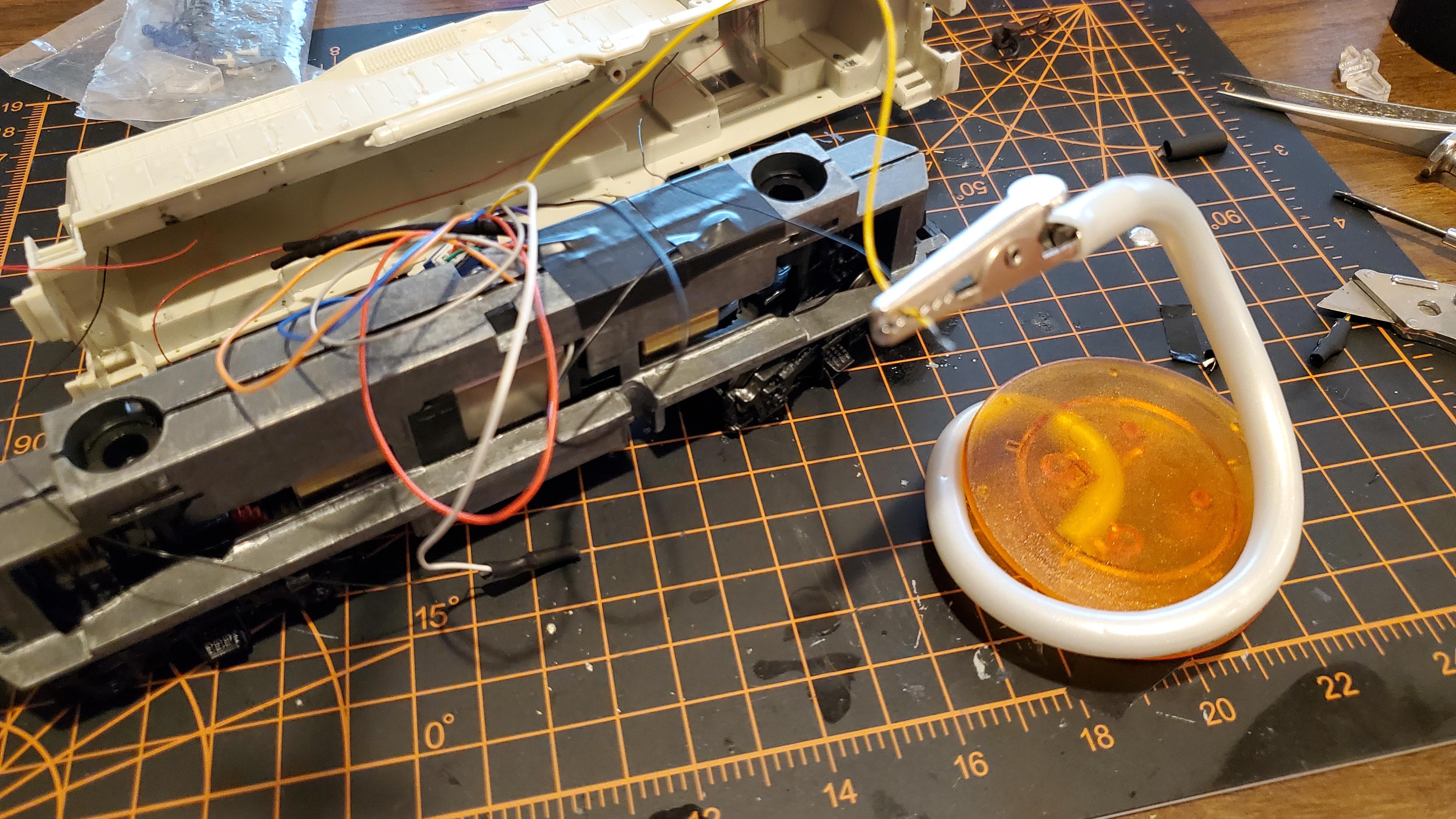
Taking the shell off the locomotive reveals an interesting approach to the inner workings of a model train:
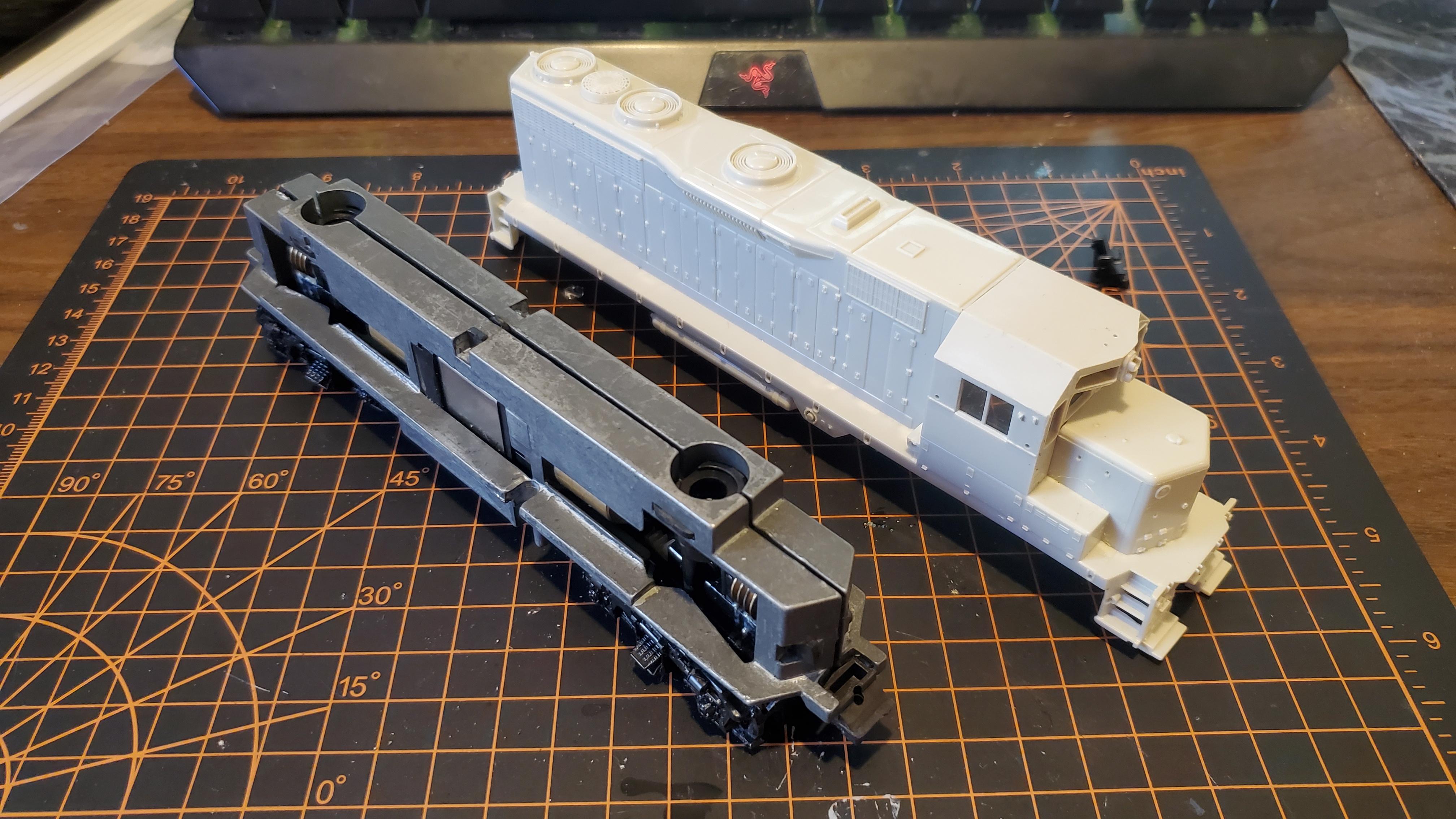
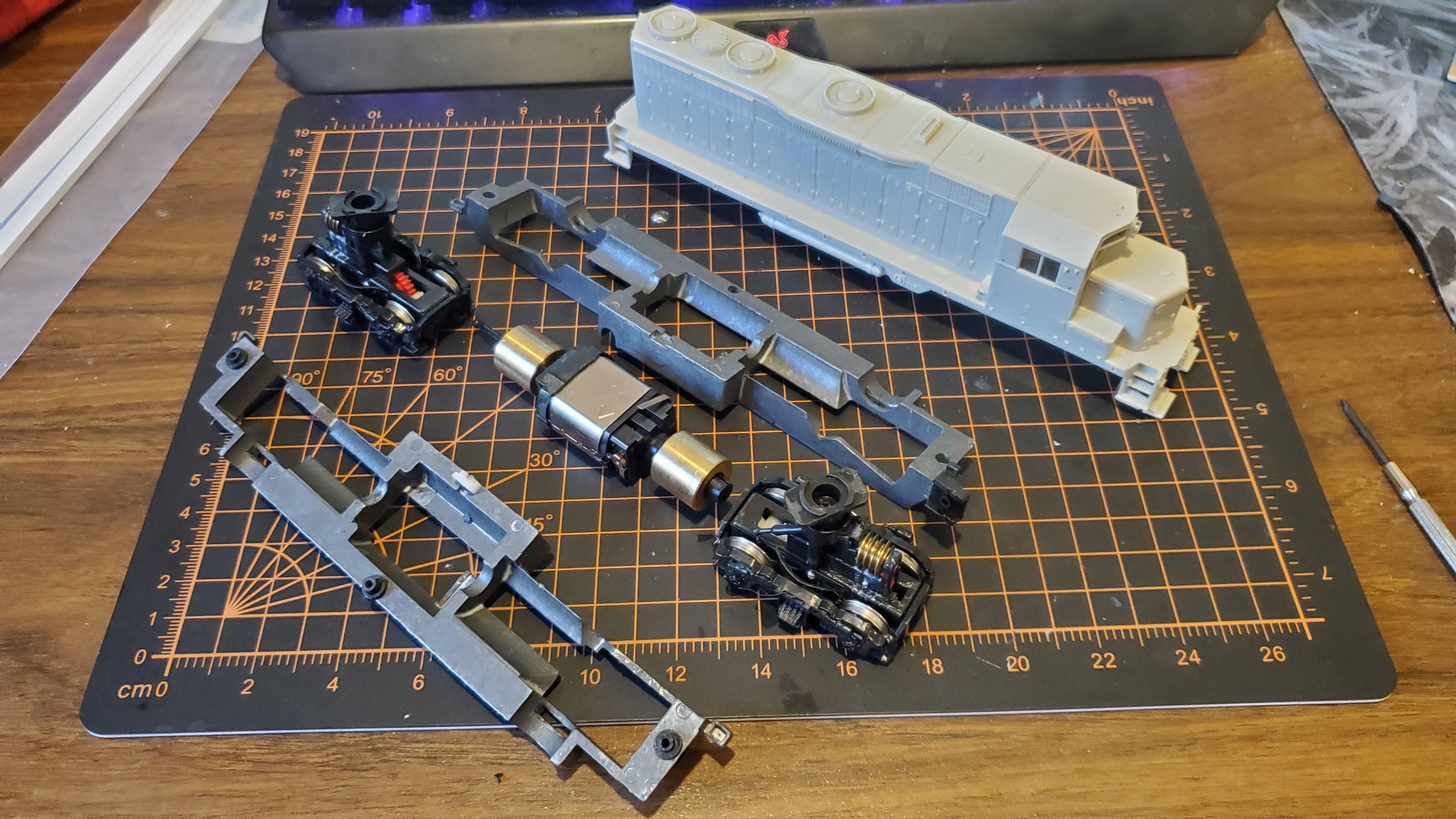
Older Bachmann locomotives, such as this one, consist of two driven trucks, driven by a can motor encased inside two large conductive weights. Power is passed from the tracks to the engine via these weights; the trucks contain little tabs that rub against the weight, transferring electricity through them to tabs on the motors. Some screws with rubber spaces hold everything together, making dismantling pretty easy.
First step of decoder installation was getting the leads (orange + grey) onto the motor. I cut the motor tabs off and soldered the wires to their point of origin. If you ever find yourself working on a similar mode, dont remove the caps, as they contain a spring that holds the whole thing together. I actually had to solder one cap into position as I went.
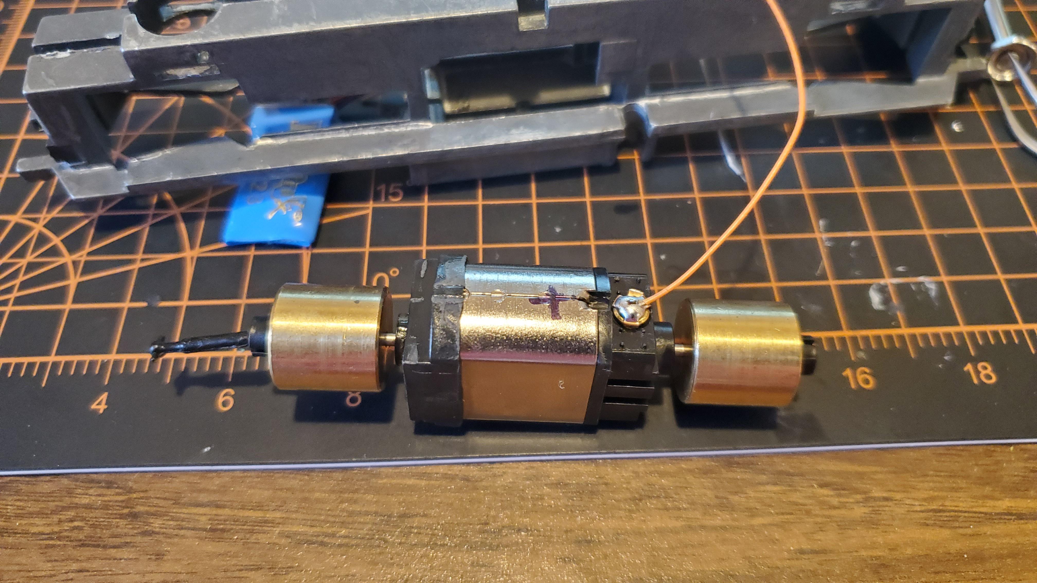
With a little more work, motor leads are in. I marked positive and negative, but in classic me fashion, I got them backwards, which will come into play later. Once the wires were in though, a clamped the track wires to my test track and tested the motor:
Yay! No burning decorder! From there, I did a test fit of the motor back into the shell, with the decoder, still mostly loose, up top. I also put electrical tape over the solder to prevent any accidental cross-wiring.
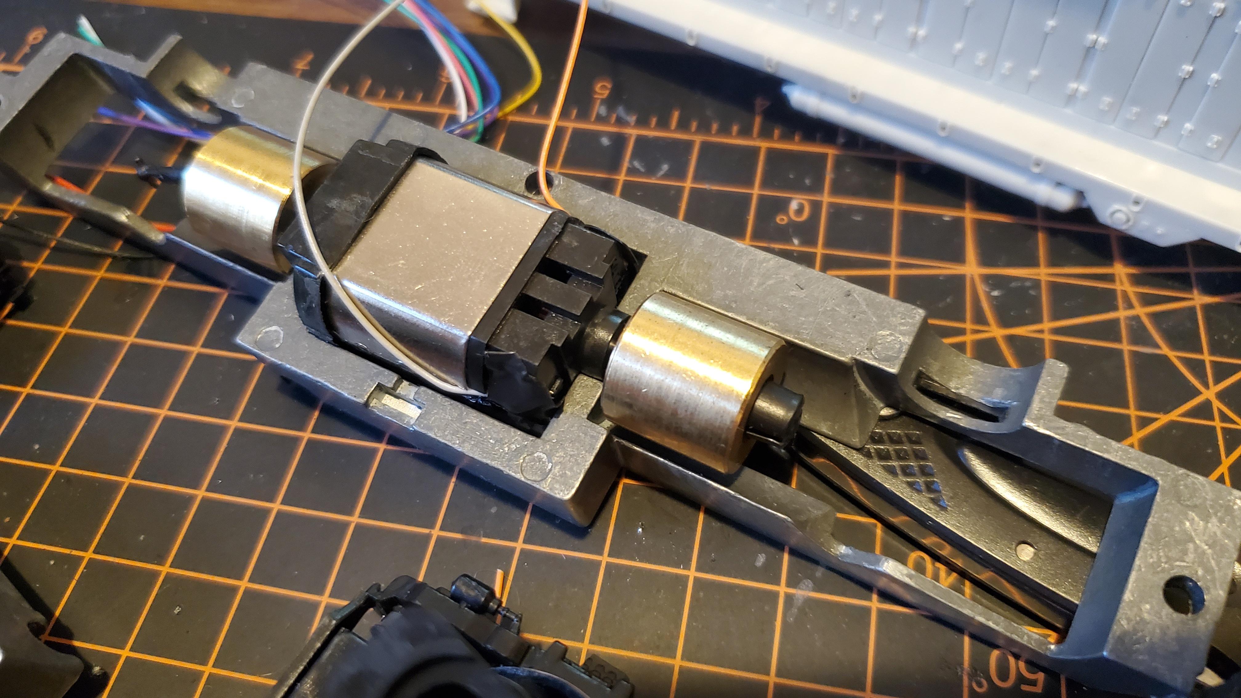
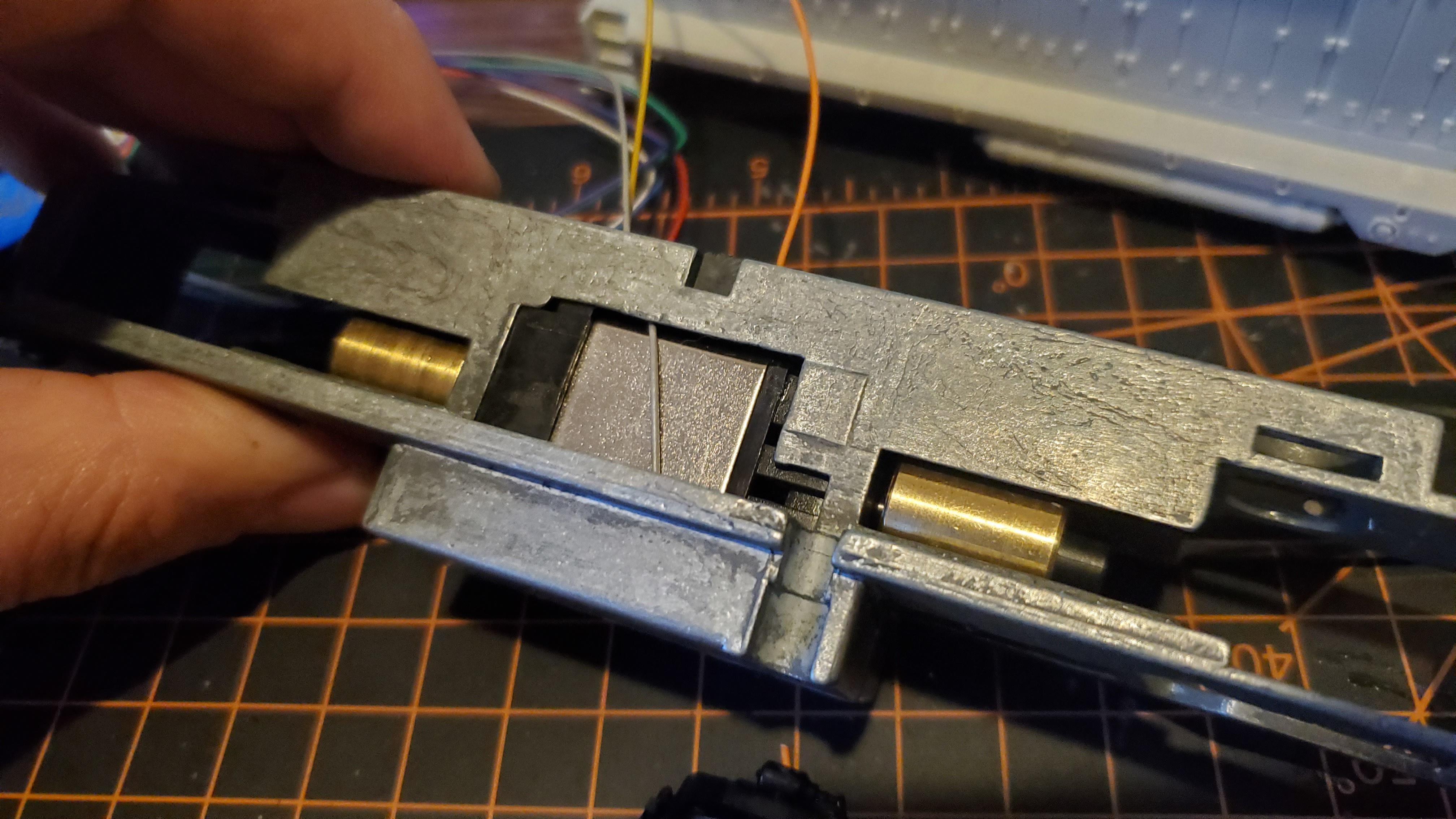
The motor fit in the weights without any issue, which was a pleasant surprise. However, mold tabs in the shell prevented the decoder from fitting just right. Thankfully they popped out with just a bit of extra force. (Note them in each of the 3 fan indents)
Motors in! Whats next?
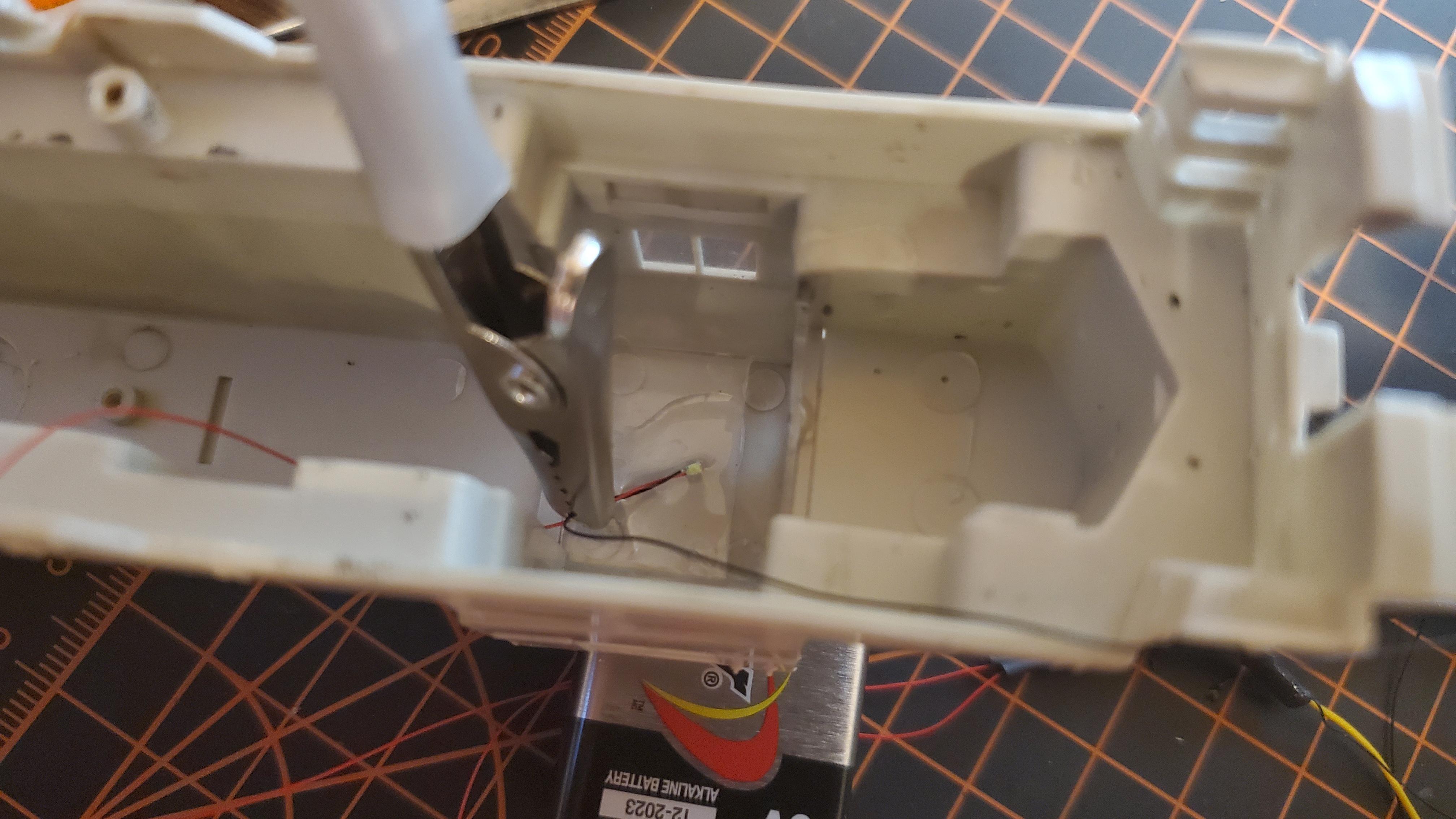
Lights! I have some tiny little LEDs with resisters ready to go, so I used them here. Soldered them into the proper decoder wires and lightly glued them into the shell.
I had footage of them up and running, but it didn't save. Finally, I used electrical tape to tape the decoders 'track wires' to the two conductive weighted. With everything figuratively ready, I decided to shove everything into the shell and got the test loop out. Time for the first official test run!
Also a surprise from the Yard Master, Livy!
Uh oh! Looks like the motor power is backwards! Luckily I don't have to fully dismantle the thing to reverse the wires, a quick modification of CV (Controllable Variable) 29, and the motor is going 'forward' on forward, as intended. But this doesn't fix the lights, sadly. So everything back out again, and I spent some time rewiring the lights, simply inverting the connections so 'back is front' and 'front is back.'
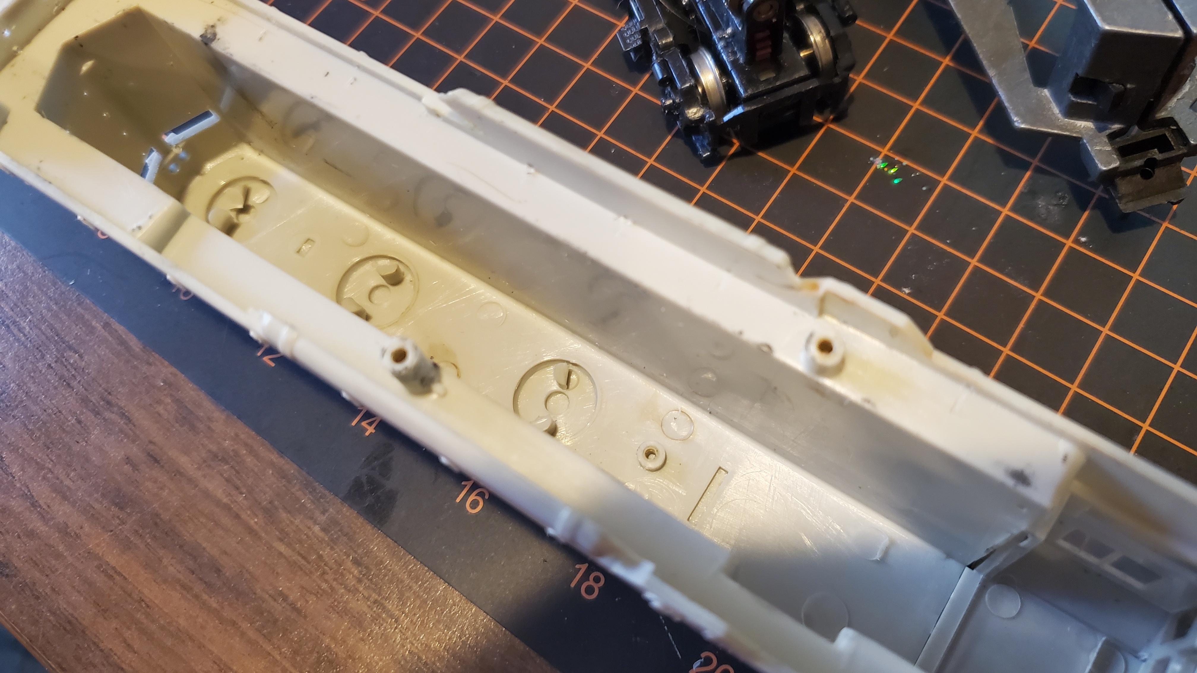
At this point, I decided it would be best to detach the lights from the shell so I can paint it without worrying about any of the internals getting jammed up with paint. So I removed the shell and decided to do one last run to make sure I didn't break the rear LED, which I had to scrape off. (The front LED is glued to the window glass, which just pulls out with ease.
This is where I made the blunder.
While these little LEDS are great for fitting into tiny spaces, they have one problem: They're exposed. Normal LEDs have protective covering over the components, and the leads can be protected with shrink wrap. When I went to run the locomotive again, the exposed back of the rear LED touched the weight, which was talking in power from the track. This caused the decoder to short, and once the decoder shorts, it's good as dead (especially one like this, that has been out of production for years.)
I had a moment of panic; I thought I'd be spending another whole day redoing this entire process. As fun as soldering is, it can be exhausting, on top of the rest of the days 'to-do's.' Thankfully, the DH123D uses a 9-PIN Wire harness and is not directly wired in. Tomorrow, I'll just have to hit up the train store for a new decoder that can take a 9-PIN and simply swap out the chips (and after I finish this post, I'll make sure to 'protect' that LED with a coat of glue). So while ending on a low note, the days not totally bust! We'll see what tomorrow brings when I try and recreate the train's paint scheme on the shell!
Day 2 (Coming Soon)
Goals for Saturday; paint the shell and purchase a new 9-PIN compatible decoder! Wish me luck!
Project Goal: Recreate the classic TF2 Train seen in Well and other maps.
Day 1
This project starts with an existing locomotive: an undecorated Bachmann Plus EMD GP35. Not the flashiest locomotive, but a nice cheap start for a project like this. I obtained this last weekend from the local youth club, gave it a test run, then shelved it till the jam start.
Today's goal was to implement all the electronics, and prep the locomotive for painting tomorrow, at the club. The decoder I started with was a DigiTrax DH123D. An older decoder, but considering its been sitting in a box for about 8 years, what better time to use it than now?
Taking the shell off the locomotive reveals an interesting approach to the inner workings of a model train:
Older Bachmann locomotives, such as this one, consist of two driven trucks, driven by a can motor encased inside two large conductive weights. Power is passed from the tracks to the engine via these weights; the trucks contain little tabs that rub against the weight, transferring electricity through them to tabs on the motors. Some screws with rubber spaces hold everything together, making dismantling pretty easy.
First step of decoder installation was getting the leads (orange + grey) onto the motor. I cut the motor tabs off and soldered the wires to their point of origin. If you ever find yourself working on a similar mode, dont remove the caps, as they contain a spring that holds the whole thing together. I actually had to solder one cap into position as I went.
With a little more work, motor leads are in. I marked positive and negative, but in classic me fashion, I got them backwards, which will come into play later. Once the wires were in though, a clamped the track wires to my test track and tested the motor:
The motor fit in the weights without any issue, which was a pleasant surprise. However, mold tabs in the shell prevented the decoder from fitting just right. Thankfully they popped out with just a bit of extra force. (Note them in each of the 3 fan indents)
Motors in! Whats next?
Lights! I have some tiny little LEDs with resisters ready to go, so I used them here. Soldered them into the proper decoder wires and lightly glued them into the shell.
I had footage of them up and running, but it didn't save. Finally, I used electrical tape to tape the decoders 'track wires' to the two conductive weighted. With everything figuratively ready, I decided to shove everything into the shell and got the test loop out. Time for the first official test run!
Uh oh! Looks like the motor power is backwards! Luckily I don't have to fully dismantle the thing to reverse the wires, a quick modification of CV (Controllable Variable) 29, and the motor is going 'forward' on forward, as intended. But this doesn't fix the lights, sadly. So everything back out again, and I spent some time rewiring the lights, simply inverting the connections so 'back is front' and 'front is back.'
This is where I made the blunder.
While these little LEDS are great for fitting into tiny spaces, they have one problem: They're exposed. Normal LEDs have protective covering over the components, and the leads can be protected with shrink wrap. When I went to run the locomotive again, the exposed back of the rear LED touched the weight, which was talking in power from the track. This caused the decoder to short, and once the decoder shorts, it's good as dead (especially one like this, that has been out of production for years.)
I had a moment of panic; I thought I'd be spending another whole day redoing this entire process. As fun as soldering is, it can be exhausting, on top of the rest of the days 'to-do's.' Thankfully, the DH123D uses a 9-PIN Wire harness and is not directly wired in. Tomorrow, I'll just have to hit up the train store for a new decoder that can take a 9-PIN and simply swap out the chips (and after I finish this post, I'll make sure to 'protect' that LED with a coat of glue). So while ending on a low note, the days not totally bust! We'll see what tomorrow brings when I try and recreate the train's paint scheme on the shell!
Day 2 (Coming Soon)
Goals for Saturday; paint the shell and purchase a new 9-PIN compatible decoder! Wish me luck!