Crowbar - an open-source editor
- Thread starter NoodleCollie
- Start date
You are using an out of date browser. It may not display this or other websites correctly.
You should upgrade or use an alternative browser.
You should upgrade or use an alternative browser.


Another suggestion, just to jot down for later: It would be nice of the selection boxes for props matched the rotation of the props instead of just expanding to fit the corners as they do in Hammer.
nightwatch
aa
- Sep 7, 2012
- 638
- 500
Another suggestion, just to jot down for later: It would be nice of the selection boxes for props matched the rotation of the props instead of just expanding to fit the corners as they do in Hammer.
While I agree with this entirely, I sometimes use the length and width to determine how far I've rotated something - if a small prop is 16.0 by 16.0 by default, i know that when I rotate it 90 degrees it will still be 16.0 by 16.0, which is useful when I've been rotating lots of items in a sequence and I don't want to have to undo a lot of work (that I might want to keep) in order to restore a prop or brush to its older orientation. This is easily solved by using CTRL+M +TAB + TAB + TAB + ### + ENTER but sometimes it's faster to rotate with the mouse instead, and when I've been doing a mixture of both it's hard to remember to switch tools to rotate when the current one will work fine.
In short, have an option to leave it the way it is as well, or perhaps some sort of additional property that shows how far something has been rotated - I know that entities have this already in their property info but as far as I am aware you can't do it for brushes. This might have to change the structure of a vmf if you want to keep it available for multiple sessions of opening/closing hammer but it might be possible to do something with comments.
nightwatch
aa
- Sep 7, 2012
- 638
- 500
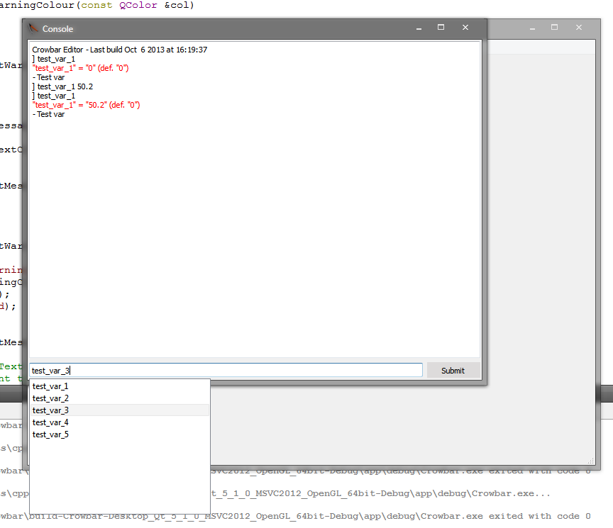
Wasn't piping a thing in Unix, and that's what made it happen in all Linux distributions?for anyone who's used Linux, I've implemented command piping so that you can use the output from one command as the input of another command.
If that's a snide tone (I might be misunderstanding), these things take time, especially when it's just been me working in-between a summer job and a university course, and a robust and extensible backbone is vital before implementing the rest.. If you'd like to help progress, you are absolutely free to jump into the source code yourself.
XFunc_CaRteR
L5: Dapper Member
- May 14, 2009
- 248
- 17
rule number 1 of tf2m is we don't use carve
/thread
seriously tho, I can c#. I might hop in at some point
I've used the carve tool to make shattered glass window planes.
Works very nicely.
You make a piece of glass, stick a cylinder into it and then hit carve. Creates a weird-looking hole. Then delete a few pieces and the remaining brushes look like chunks of sharp glass.
For anyone interested, I've written down some more of my thoughts on the rendering process:
To render graphics, we need to provide OpenGL with vertex data (ie. the position, colour, etc. of each vertex). OpenGL also uses vertex indices, which is simply a series of numbers which relate to the order in which to draw vertices; this means that if you wanted to draw two triangles which share an edge (and so share two vertices), you can specify all five vertices required for both the triangles and then specify the vertex indices in the order you want them drawn (1, 2, 3 for the first triangle, 2, 3, 4 for the second triangle) instead of having to duplicate all the vertex data for the shared vertices in order to create two new ones.
This paradigm means that we need two sections of memory on the GPU: one for the raw vertex data (a Vertex Buffer Object, or VBO) and another for the array of vertex indices. When rendering, the vertex index array is traversed and each index is interpreted as an offset from the beginning of the VBO portion of memory - vertex 0 has an offset of 0, while vertex 5 would have an offset of 5 vertex "footprints" from the beginning. If each set of vertex data were 20 bytes long, for example, vertex 5 would start 5 x 20 = 100 bytes into the VBO portion of memory. OpenGL would move 100 bytes into the VBO and then read the vertex data from that position in order to know the position/colour/whatever of vertex 5.
So how do we translate brushes into vertices in memory? A brush, as I see it, can be decomposed into multiple different elements, ending up with simple vertices. A brush can be thought of as a collection of faces, each with a corresponding normal. Faces in turn can be thought of as one or more adjacent coplanar triangles (referred to here as polygons). Polygons are a collection of exactly three distinct edges which form a closed loop, and each edge is a collection of exactly two distinct vertices.
The hierarchy of brush components is therefore:
Brush -has many-> Faces -which can have many-> Polygons -which have three-> Edges -which have two-> Vertices
Note that we could have cut out faces entirely and gone straight from brushes to polygons, but since a brush face is rarely a single polygon (often two, as lot of faces are rectangular) it is useful to group sets of adjacent coplanar polygons together so that, if one is selected in the 3D view, for example, it is easy to select the whole brush face as the user sees it.
Going back to OpenGL: when allocating memory for the VBO, the size of the memory we want to allocate must be known. This can be accomplished by selecting a maximum number of vertices a brush is allowed to have, and a maximum number of brushes allowed in a map. The size of the VBO then becomes (max brushes) x (max vertices per brush) x (total data required for a vertex). In order to maximise the use of memory for the counters we will use to store the brush and vertex numbers, a good maximum brush count is 65,536 (the number of values specifiable by an unsigned 16-bit variable) and a good maximum vertex count per brush is 256 (the number of values specifiable by an unsigned 8-bit variable).
So, we know we are allowed, in the worse case, 65,536 brushes in a map, each of which could have 256 vertices. This means we can calculate the exact amount of memory required to store all the vertex data we could ever possibly need: if we assume, for simplicity, that each vertex is 12 bytes long (4 bytes for each of the x, y and z co-ordinates), this means the total amount of memory we need to allocate for vertices is 65535 x 256 x 12 = 201323520 bytes, which is roughly 190 megabytes. This is well within scope of the gigabytes of graphics memory available on modern cards, but might push the boundaries for older, 256/512mb cards.
But we also need to allocate memory for the vertex index buffer! To do this we can set a maximum polygon count for a brush. In the worst case, a brush could have a total of 254 polygons by sharing many of its 256 vertices between these polygons - you can check this by the fact that if you construct a polygon with three vertices, you only need to add one extra vertex (and share any two other vertices that already exist) every time you want to add a new polygon to your collection. Since each polygon requires three vertex indices, and each index is stored as an 4-byte integer, the maximum number of bytes a brush's vertex indices could possibly occupy is 254 x 3 x 4 = 3048 bytes per brush. This works out at a total of 65536 x 3048 = 199753728 bytes for the entire buffer, or again roughly 190 megabytes.
To upload the vertex data to the VBO, we need to know where to put each vertex. Luckily, with the brush structure above we can calculate this. Since we need to limit the maximum number of brushes allowed, we can number each brush in the map starting from 0. We can also number each vertex in a given brush, again starting from 0. This means that brush 0's vertex 0 is stored at the very beginning of the VBO. For vertex 10 of brush number 7, the calculation is simple: firstly we find the offset from the beginning of the VBO at which this brush's vertex data should start. In this case, if we again assume each vertex is 12 bytes in size, the offset is 7 (brush number) x 256 (maximum number of vertices allowed per brush) x 12 (number of bytes per vertex) = 21504 bytes from the beginning. We then find the offset of the vertex from the beginning of the brush: 10 (vertex number) x 12 (bytes per vertex) = 120 bytes. Adding the two, we know that vertex 10 of brush 7 should reside 21504 + 120 = 21624 bytes from the beginning of the VBO.
Vertex indices are similar: vertex 10 of brush 7 corresponds to exactly this vertex-sized "slot" in memory inside the VBO. To calculate this slot (and therefore the vertex's "index" when passed to OpenGL), we do 7 (brush number) x 256 (maximum number of vertices per brush) to get to the beginning of the brush's data, and then add 10 to get to the 10th vertex in that brush. Note that we don't multiply by 12 here because we are not looking for the offset in bytes; instead, we are looking for the offset in terms of the number of vertex-sized chunks we have to travel from the beginning of the VBO until we reach the chunk that corresponds to our vertex.
The VBO and index buffer are slightly different in terms of their layout. Since the VBO is only referenced by the indices we provide to the index buffer, we don't need to worry about the fact that most brushes will probably have nowhere near 256 vertices in them. The empty space in the VBO should (as long as we specify our index offsets correctly) never be read, so the memory can remain "sparse" (ie. fragmented). The index buffer itself, however, will be read sequentially from start to end by OpenGL, and as such should not have any "empty" space within it - all vertex indices provided should be contiguous.
Now that we know where to upload the vertex data into memory so that OpenGL can read it later, we need to decide how often to do this. Since transferring lots of data to the graphics card all the time can slow things down, ideally we'd only want to do this when required. OpenGL does provide functionality for updating only specific sections of the VBO, but how would we choose which bits to update?
One method would be to record the highest and lowest numbers of the brushes that were changed on any given frame, and update all of the memory in-between these brushes. This would use only a constant amount of memory to record which brushes were changed, but in the worst case (brush 0 and 65535 being changed) would require the whole VBO to be updated simply because two brushes had been modified.
A different method would be to use a map (basically an ordered list) to record the brushes which were changed in a given frame, and use the values stored in the map to update the relevant parts of the VBO. This would be a better method, and could be optimised by merging consecutive brush numbers into one big update (for example, if brushes 1, 2, 3 and 4 changed, instead of calling four different updates we could just update all of the memory between brushes 1 and 4 inclusive). The one problem with this method, however, is that in the worst case it would result in a lot of small updates to fragments of the VBO (for example, brushes 1, 3, 5, 7, 9...) which may be slower than simply updating the whole VBO in one go. To mitigate this, an extra value could be passed in to specify the gap between brush numbers which should be considered large enough to split up one large update call into multiple smaller calls. For example, with a gap value of 2 the sequence 1, 3, 5, 7, 9 would be updated in one block, whereas the sequence 1, 4, 7, 10, 13 would be updated in 5 separate calls.

nightwatch
aa
- Sep 7, 2012
- 638
- 500
I think I followed most of it but I know nothing about graphics cards so I'm not sure I'm really getting it. Seems like a massive waste of space though in the VBO, I feel ike there ought to be a better way to hold that data in an organized manner without scattering it between long unusable chunks of empty memory.
I guess it might be possible to re-create the VBO depending on how many brushes there are (and same for the index buffer) but I'm not sure how expensive creation vs. updating is.
henke37
aa
- Sep 23, 2011
- 2,075
- 515
For the record, the vertexes need to store more data than the position. They need the UV coordinates. We can ignore fancy shading in the editor, but texture alignment is mandatory.
Do note that faces can have more than four sides, like the lid faces of a cylinder.
As for things like highlighning of selected brushes and tinting instances, that can be done with shader constants.
Do note that faces can have more than four sides, like the lid faces of a cylinder.
As for things like highlighning of selected brushes and tinting instances, that can be done with shader constants.
The UVs are a good point, I'd forgotten about them. The component method should be able to scale as required to faces with many polygons.
Since texture alignment is relative to the face as opposed to the vertices I may be able to pass UVs in as uniforms depending on the face that's being rendered, but yeah that is a good point. I'll need to work out a way of allowing for it.